Showing posts with label led. Show all posts

Sunday, November 6, 2011

Calculus and Christmas Lights (or, the flicker problem)

This is a problem that I was wrestling with a little over year ago, building an LED prop for a friend's movie. That was before I started taking math classes...

To simplify it, many "efficient" light sources are efficient because they flicker- they are not constantly "on" like incandescent lights. Filmmakers love incandescent lights because they don't flicker (see note).* More efficient sources like HMI's are very carefully engineered to flicker in sync with the camera shutter, so that the camera doesn't notice the flicker. And most LED light sources are battery powered with a constant DC voltage, so there is absolutely no flicker.

This is where we come to the problem of LED Christmas lights- long strings of LED lights in series, that plug into AC power. LED's don't normally run on AC power because the voltage is too high, and LED's are at their hearts, diodes, which means they only pass current in one direction. Most LED circuits you plug into your wall go through both a transformer, to step down the voltage to a safe level, and a rectifier, to invert the negative half of the AC wave, and provide a constistent DC power supply.

But LED Christmas lights are an ingenious solution to this problem... almost. They take 60-70 LED bulbs, and wire them in series. LED's tend to drop about 1.2-2.0 volts individually, but put 60 in series, and you've got yourself a circuit that can drop 120v. That eliminates the transformer (wall wart) from the equation. However, it does not adequately address the flicker problem. LED's are still diodes, and if you have 60 of them, all pointing in the same direction, they will only be "on" when the AC wave is positive. That means, they will only be on for half of the AC wave.

You may notice this flicker if you look with the corner of your eye. The first time I noticed this was rigging on the set of a pretty big movie that will go unnamed. If you can see a light source flicker with your eye, a movie camera will definitely pick it up, and possibly ruin the shot (I wonder how much it cost to fix that...).

That's because movie cameras generally shoot at 24 frames per second, and the shutter speed is 1/48 of a second. That means that the camera only sees HALF of the time you're filming (they say half of every movie is darkness), and the camera ONLY sees things 1/48 of a second at a time. This being a film camera with a mechanical shutter. Digital cameras (and digital shutters) make things even weirder.

Hence, some math:


I've approximated the 60Hz AC power with the red sine wave, and the 24 fps camera shutter with the green sine wave. The LED's are only on when the red wave is positive, and shutter is only open when the green wave is positive (shutter speed is calculated from when the shutter is half-open to half-closed, probably because it's constantly moving).

So each positive half-wave of the green curve is one frame in the movie. The exposure (brightness) of the LED's in each frame would be equal to the intersected area beneath both curves, when both are positive. Keep in mind there are 24 frames per second:


This is done by adding up piecewise integrals. A1 is the "brightness" of the first frame, and A2 is the "brightness" of the second frame, which is slightly more than the first. Keep in mind these are abstracted, and don't actually correlate to any real measure of brightness. However, the proportions should be accurate, and Frame 2 is 18% brighter than Frame 1. That's not good.


Another interesting thing is that 5 AC power cycles = 2 camera shutter cycles. The waves line up every 2 frames, or 5 flickers. So all the even frames are the same, and all the odd frames are the same- which means every other frame is 18% brighter than the one before it. There's your flicker!

Thanks to Maple for doing the heavy lifting for me. I need to figure out how to code in Maple. It would make my life much easier...

*Note: Incandescent lights also "flicker" because they are on AC power, but they are so hot (read: inefficient) that the flicker is negligible.

Saturday, October 9, 2010

Shooting the Moon


Live-blogging the shoot!

Using Processing to control the moon. The physical controls are nice, but limited in their capabilities. Very handy for Backpack Mode, so the kid can run around in the woods with the thing. But Processing allows for much more fine control, and better random number effects (and processing speed!) too.

Saturday, September 18, 2010

Battery Stuff

Just a note- using a DeWalt XRP 14.4v battery for the "Backpack Mode" moon (portable & self contained, so the kid can run around with the moon lit up).

Ran most of the day. Forgot to meter the battery at the start of the day, but about halfway through the day, it metered 15.7v, and by the end of the day it was only down to 15.6v. I guess the LED load pales in comparison to the DeWalt drill motor... I have a feeling this will last for a while, despite not having done the math to confirm this fact...

Also can't find the mAh rating for the battery, but maybe I'm not looking hard enough.

Shoot day 2 coming up... just found out the moon has to get wet. That should be fun...

Friday, September 17, 2010

The Controls for the Heart of the Moon, v2.0

04:17am Sept 17- Finished the enclosure, and [hopefully] all the troubleshooting for the controls. Not taking it apart again, it took long enough to squeeze it in there...

I feel like I'm back in school pulling an all nighter to finish a project on time... which is pretty much what I'm doing, minus the school part.

I promise better pictures, and better writing, after I get some sleep...

Good night.

EDIT 00:43am Sept 18:

Four hours of sleep, then driving two hours to stay at a friend's house to make a movie for the weekend. I feel like I'm in college again... oh wait, I am.

Much progress tonight... figured out, in record time, how to get Processing to control the Arduino dimmer (and thus push my painstakingly constructed hardware controls into obsolescence, almost).

The manual controls will suffice for simple "breathing" effects loops, and they're key for self-contained Backpack Mode, but being able to control the finer aspects of the dimming cycle from Processing will really come in handy when we get into making the moon act like it's sick on the next shoot.

Figured out why the dimming has been so jerky- I've had it outputting a lot of debug data over Serial, which has been slowing down all the loops. So now that it's working, I don't need the debug data and now it's much smoother- italics used to emphasize smoooooothness.

The one issue I'm having (and it very well might be a software bug...) is that the new TIP31 transistor is not behaving the same as the old one... it seems like it goes from 0-100% brightness in the first 10 or so steps of the PWM (of 255 steps)-

MS Paint is probably the only thing I miss from my Windows days...

So we have the batteries charged and are gearing up for Shoot Day 1 tomorrow... time for bed.

Friday, July 30, 2010

New York, I love you, but you're bringing me down...

Long story short, while loading up for the shoot this weekend, we left the rental car unattended, in broad daylight, on a busy street, for no longer than 5 minutes, only to return to a smashed window and a few bags missing.

Unfortunately, those bags happened to contain the director's laptop and personal effects, the cinematographer's Canon 7D, $3,000 worth of rented lenses, and associated support gear (which is not cheap), two Moon props, and all of the associated electronics. And a duffel bag full of my clothes. And my hammock.

I am kind of at a loss for words... but at least my stuff is replaceable. While it took roughly 1.5 months to develop the Moon hardware, it only took a few days to build it once I got it all figured out. And there are certainly improvements to be made for Version 2.0.

But if anyone knows a way to track a missing laptop (MAC address? anything?), or a seedy pawn shop in Brooklyn where nice cameras and MacBooks sometimes turn up, my friends would be much obliged.

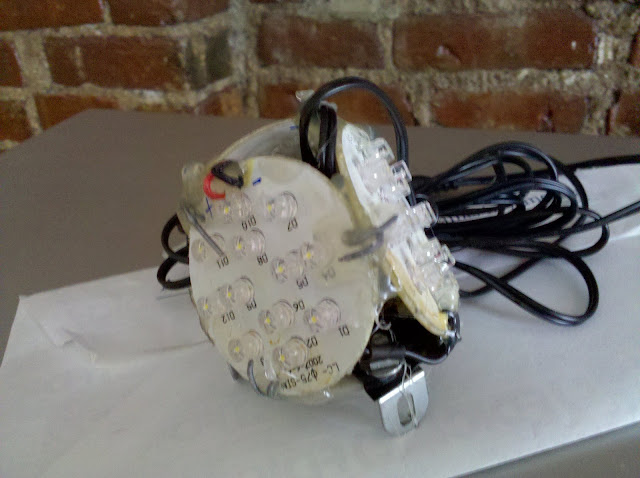
In the mean time, one more picture of v1.0. This was the first LED puck light that I "hacked" apart... and it kind of shows. It wound up being the base of the Lunar Lander... note the blue smudges around the screws. I bet you've never seen someone use LocTite on an Erector Set before. I think for v2.0, I might spec my own LEDs. Forget vomit green Home Depot lights– v2.0 will actually be color correct 5600K.

Thursday, July 29, 2010

The Eagle has Landed

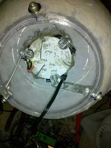
Ain't she pretty? The lighting is a little more consistent with the LEDs mounted more toward the center of the moon.

Note the screw at the very bottom of the frame. I drilled three holes, using five different drill bits, starting with 1/16" and going up to 5/32", in 1/64" increments, to avoid cracking the plastic. I feel like there will be a job waiting for me at BP once they see this...


This is the completed "Lunar Lander" module (it really looks like it with the legs attached :) It is secured with steel bailing wire, copious amounts of hot glue, and LocTite (actually, Permatex Threadlocker, but commonly known as LocTite). If this sucker comes apart, I will go jump in the lake myself. I just hope I don't have to take it apart to fix it... but copious amounts of solder, and hot-glue reinforced wire joints ought to prevent that from happening.

I must admit I am impressed with the strength of the hot glue, combined with its slight elasticity, to provide a very strong, but shock-absorbing joint.

I also must admit that I am NOT impressed with Home Depot and their child brand Hampton Bay, as far as product consistency goes. The first light I bought had a pretty bluish-white glow, so I bought a 3-pack to complete the pyramid. The 3-pack, however, though it came from the same shelf in the same store, has a really hideous green cast to it. We'll probably have to correct it with some Minus Green gel if we can find it... so if you buy these for your house, beware, they might have a vomit-green color cast to them... not so good for kitchen cabinet under-lighting, but might match your fluorescents!


This is a view of what was originally going to be the "dark side of the moon," but it is now lit for 360˚ coverage... in Three-Dee... so really 360^3 degrees. Right? Why not...

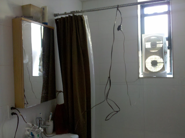
And finally, my way of removing solder (and hot glue) fumes from the air. Might I add beforehand, DO AS I SAY, NOT AS I DO:

Obviously, DO NOT DO THIS if you (or anyone else with keys to the apartment) is planning on taking a shower any time soon. Please note that the extension cord is knotted around the shower curtain bar, thus preventing anyone from closing the curtain completely and making it quite obvious even to the lay-person that it is not safe to shower right now, if only for the sake of modesty.

However, since the cord is knotted up high where the water should (REPEAT: "SHOULD") not touch it, it is not completely unsafe to shower with this configuration. And it is plugged into a GFCI outlet ;)

I do wish we lived in a world where jokes did not require big bold disclaimers, but, in closing, DON'T RUN EXTENSION CORDS THROUGH YOUR SHOWER, THAT WOULD BE REALLY DUMB, ESPECIALLY IF YOU ARE A PROFESSIONAL ELECTRICIAN!

;)

Wednesday, July 28, 2010

All in a day's (month's?) work...

Today was a very busy day...

Soldered the control board. Six 100k pots in parallel might be conflating Ohm's Law and Murphy's Law, so I'll have to figure that out...


The offending area...

This one is for all my Grip Brothers (and Sisters), demonstrating the proper use of a Cardellini clamp. I do wish I had a knuckle to go in between though...


And finally, a first glimpse at an [almost] finished product :)

Tuesday, July 27, 2010

It's nice to have the right tool for the job every once in a while...


Saves you from having to literally "hack" your way through things, and makes the end result just a little bit prettier...

This is the switchboard for the LED dimmer, which I am really excited about.

Counting down, 3.5 days left to finish it...

Wednesday, July 21, 2010

The first thing I've built that I've been legitimately afraid of plugging in-


I've had a slight fear of large capacitors ever since I took apart a 220v camera flash circuit when I was a child... lesson learned.

Hence the cardboard box "blast shield" for lack of anything better... Yes, cardboard is flammable, thank you for pointing that out. But I decided I was much more prepared for a small electrical fire than for chemical burns. Safety glasses, bucket of water, and thick soled shoe (to stamp it out) at the ready, I [reluctantly] flipped the switch. Luckily my fears were much exaggerated, and nothing jumped except for the needle on the meter.

However, it's still not working right... I am getting 21.7v dc out of a 16.2v ac input... Possibly because there's no load... but until I figure out this over-voltage thing I'm reluctant to hook anything up to it...
Ideas?

Thursday, July 8, 2010

If I had an oscilloscope, this is what it would look like.

Sadly, though, I don't have one. So I spent the day figuring out in theory why my lights are flickering. But I think I've found the problem, through roundabout and purely theoretical equations. Right now I really wish I hadn't slept through 3 years of high school math...

Briefly, this shows 1/48 of a second, the exposure time (Tv, if you're a Canon person) for a movie camera shooting at 24 frames per second (triangle wave). The effective exposure time is when the shutter is at least 50% open, exposing light to the film/sensor (thanks M&P!).

The tall sine wave is 120vac power at 60Hz, with peaks at 120Hz. I drew all the peaks as positive, as we're only concerned with "on" and "off" here, not polarity. This is the "flicker rate" of an incandescent bulb, but they don't really flicker due to a sort of "heat momentum" that carries the light through to the next peak. LEDs, being much more efficient, however, do not have this momentum, so they are much more prone to flicker.

The very short arches are the 12vdc rectified power, with positive peaks also at 120Hz. But the taller 120v peaks are easier to see, so we'll use those for reference. The vertical axis is not necessarily to scale, as we're comparing a lot of different things here.

The gray bars represent the PWM dimmer signal, at 1kHz. The width of the bars shown is at 100% duty cycle; as the light is dimmed down, the bars would get narrower. This is the amount of time that the power is "on" to the LEDs. The positive bars are "on time" and the negative bars are "off time."

Now, for why I've spent so much time doing this: The problem is that the LEDs are flickering visibly toward the low end of the PWM dimmer (picture much narrower gray bars). This is no good for camera. I had thought the problem lied with the PWM frequency, or the fact that I broke the legs off the rectifier's smoothing capacitor.

But it appears now to be the latter. If you look, there are 2 dips of the 120Hz power within the exposure time. Even though the PWM may be up full (100% duty cycle), if the input power is rising or falling, it is not putting out 100% brightness. If we assume, like the effective shutter speed, that the LED is only effective at 50% output or greater, the gaps widen significantly, and the flicker becomes even more apparent.

The Arduino PWM can allegedly go up to 64kHz, which is great, but without a clean DC power source, it wouldn't make a difference. Too bad I exploded the replacement capacitor today... apparently there is good reason behind the adage "don't plug it in while the power is on..."

Tuesday, July 6, 2010

LED Project 1

Before:

Current scheme:

After:

Sadly, the capacitor is no longer with us, due to an accident...