Sunday, November 6, 2011

Calculus and Christmas Lights (or, the flicker problem)

This is a problem that I was wrestling with a little over year ago, building an LED prop for a friend's movie. That was before I started taking math classes...

To simplify it, many "efficient" light sources are efficient because they flicker- they are not constantly "on" like incandescent lights. Filmmakers love incandescent lights because they don't flicker (see note).* More efficient sources like HMI's are very carefully engineered to flicker in sync with the camera shutter, so that the camera doesn't notice the flicker. And most LED light sources are battery powered with a constant DC voltage, so there is absolutely no flicker.

This is where we come to the problem of LED Christmas lights- long strings of LED lights in series, that plug into AC power. LED's don't normally run on AC power because the voltage is too high, and LED's are at their hearts, diodes, which means they only pass current in one direction. Most LED circuits you plug into your wall go through both a transformer, to step down the voltage to a safe level, and a rectifier, to invert the negative half of the AC wave, and provide a constistent DC power supply.

But LED Christmas lights are an ingenious solution to this problem... almost. They take 60-70 LED bulbs, and wire them in series. LED's tend to drop about 1.2-2.0 volts individually, but put 60 in series, and you've got yourself a circuit that can drop 120v. That eliminates the transformer (wall wart) from the equation. However, it does not adequately address the flicker problem. LED's are still diodes, and if you have 60 of them, all pointing in the same direction, they will only be "on" when the AC wave is positive. That means, they will only be on for half of the AC wave.

You may notice this flicker if you look with the corner of your eye. The first time I noticed this was rigging on the set of a pretty big movie that will go unnamed. If you can see a light source flicker with your eye, a movie camera will definitely pick it up, and possibly ruin the shot (I wonder how much it cost to fix that...).

That's because movie cameras generally shoot at 24 frames per second, and the shutter speed is 1/48 of a second. That means that the camera only sees HALF of the time you're filming (they say half of every movie is darkness), and the camera ONLY sees things 1/48 of a second at a time. This being a film camera with a mechanical shutter. Digital cameras (and digital shutters) make things even weirder.

Hence, some math:


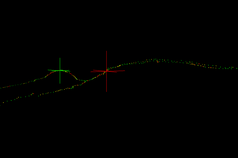
I've approximated the 60Hz AC power with the red sine wave, and the 24 fps camera shutter with the green sine wave. The LED's are only on when the red wave is positive, and shutter is only open when the green wave is positive (shutter speed is calculated from when the shutter is half-open to half-closed, probably because it's constantly moving).

So each positive half-wave of the green curve is one frame in the movie. The exposure (brightness) of the LED's in each frame would be equal to the intersected area beneath both curves, when both are positive. Keep in mind there are 24 frames per second:


This is done by adding up piecewise integrals. A1 is the "brightness" of the first frame, and A2 is the "brightness" of the second frame, which is slightly more than the first. Keep in mind these are abstracted, and don't actually correlate to any real measure of brightness. However, the proportions should be accurate, and Frame 2 is 18% brighter than Frame 1. That's not good.


Another interesting thing is that 5 AC power cycles = 2 camera shutter cycles. The waves line up every 2 frames, or 5 flickers. So all the even frames are the same, and all the odd frames are the same- which means every other frame is 18% brighter than the one before it. There's your flicker!

Thanks to Maple for doing the heavy lifting for me. I need to figure out how to code in Maple. It would make my life much easier...

*Note: Incandescent lights also "flicker" because they are on AC power, but they are so hot (read: inefficient) that the flicker is negligible.

Wednesday, August 24, 2011

RoboRadar

Working on making a radar type sensor with a Parallax rangefinder mounted on top of a servo motor. Left is raw distance data (2-300 cm), drawn in polar coordinates, and right is *supposed* to be corrected into rectangular coordinates. But they look eerily similar so I'm not sure that's working yet.

But the big accomplishment is the beginnings of an object detection system, as note by the white boxes. Basically if the points are close enough together, there must be an object there.

The problem is figuring out how close is close enough. As you can see, there are lots of tiny boxes that should probably be combined into one big box, as well as really big boxes that are overlapping smaller discrete objects.

Too many little boxes are a problem for memory & speed (right now it's sensing over 4,000 objects, but there are only 90 dots!). It would make more sense to combine them into one "wall" object, with the same effect.

The really big box is a problem, because the robot would see that entire area as an object, and avoid it; it would never move forward.

The moral of the story: weak object detection makes for slow, paranoid robots. Smarter = faster = more risk tolerance = more exploration!

Tuesday, August 23, 2011

Richard Serra Driving

Pieces of a Richard Serra sculpture driving toward the George Washington Bridge...

Finally, some art in the suburbs...

Thursday, July 28, 2011

Inspecting the Internet Plumbing

Ever wondered how a website gets from there to here? Me too.

Especially when "there" is halfway around the world...


The Black Dot is Brooklyn (because Brooklyn is too cool for silly colors). The white dots in the upper right are a website in Italy. The other white dots are the servers in between that the website had to travel through to get to me.

The signal went from New York to New Jersey (which are so close they overlap), to California out left, and then magically to Italy.

Pay no attention to the line going straight through the Earth. I actually have no idea how the signal got from California to Italy. Must be either a satellite or an underwater cable... but an underwater cable wouldn't go direct to Italy... very curious indeed.

Also, the white dot on the lower right is an anomaly. It actually represents the IP 0.0.0.0, which is a dummy IP (which I believe is my computer talking to my router). Since it's a dummy IP, it was assigned (0,0) as a location, and so it pops up at the intersection of the Prime Meridian and the Equator.

Other points of note are Greenwich, England (green dot on the Prime Meridian), and the Magnetic North Pole (yellow dot on the yellow meridian). The rest are cities around the world.

At some point I will have to figure out how to add continents and draw arcs around the world rather than tunnel straight through it... however convenient that might be. For some reason my problems keep coming back to moving things around spheres...

Saturday, April 30, 2011

A Different Perspective

Finally getting things to line up... but the perspective is not quite right. It looks fine on the top half of the mountain, but the horizontal trail should be much lower; in fact, part of it is behind the camera, which just ain't right...
This is the same view with placemarkers drawn in: the green cross is the GPS peak of Blackhead, which is the point where the photo is inserted. The red cross is the camera position (with compass and XYZ directions drawn in), and the pink cross is the peak of Black Dome mountain. There enlies the problem-

This is a side view of the whole thing, looking North. The red cross is still the camera, and the white line is where it's looking. Black Dome is behind the camera, but somehow the camera still sees it. I think this has to do with the ortho() function, again because the perspective on the path is not quite right. I've tried adjusting the clipping planes, but that doesn't change the perspective, only what renders and what doesn't render. So how the camera is seeing behind itself, I don't know...

But this is what it looks like with the "standard" perspective:

And this is where I think the trail should be:

Wednesday, April 27, 2011

Into the Void... aka Progress!


Making progress orienting the OpenGL virtual camera, and fixed the rotation of the image so it's [very nearly] square to the virtual camera. Note to self: degrees are not the same as radians.

In theory, all I need to do is make some fine adjustments to the image orientation to compensate for the pan and tilt of the real camera (when the picture was actually taken). And then get it to scale properly- the image should take up the whole gray area. And hopefully the perspective will correct itself with the scaling... hopefully being the key word.

Wednesday, February 23, 2011

Blackhead (annotated)

This is Blackhead Mountain in the Catskills, from a lookout on Black Dome, and somewhere in the middle is the trail that links the two. If I can figure out the scale of the photo, and the direction that the camera is pointing, I can use my GPS log to draw the trail.

I know the GPS position of the Blackhead peak and the camera, and using those I can calculate the distance and bearing between the two. But since the peak is off center, I need to figure out the direction the camera was pointing, even though it's only off by a few degrees.

The peak is offset by 114 pixels horizontally (the black triangle). If I can figure out the scale of the photograph accurately, I can use this to figure out angle the camera is pointing. Of course, the original image is much larger, but the ratios should stay the same.

If I can figure out the scale and rotation of the image, I should be able to line up the GPS log of the trail with the picture...

This is a crudely oriented view of the GPS trail. The red cross is the camera position, and the green cross is the peak of Blackhead. So all I really need to do is line up those two points over the picture... simple enough, right?


Ultimately it should look something like this, but with more picture and less black void...

Monday, February 7, 2011

Mt. Hight, New Hampshire

3D view
Elevation vs. Time


Total Time: 5:51:49
7.93 miles
1.36 miles / hour (not taking stops into account)

1472.1 feet (base elevation)
4706.5 feet (peak elevation)
4079.3 feet (elevation gain)

Red: <>Yellow: <>
Green: > 1.0 m/s